This blog will continue with the practical workbook we did in class last week. We will have an in depth look at capacitors, transistors op amps and ill be looking at terms like beta and saturation.
Experiment number 5: Capacitors
What is a capacitor? A capacitor is a passive component that stores energy in an electric field. It consists of two conductors/plates separated by an insulator. When potential differences (voltage) occur positive charge collects on one plate while negative charge collects on the other plate. Energy is created and is stored on an electric field on the insulator. The size of the energy able to be stored is called the capacitance and is measured in farads.
In simple terms a capacitor absorbs current until it reaches a certain value and then in stores it until it’s required. It usually also increases the voltage so that it has a much bigger output.
Types of capacitors
Here is a list of the different types of capacitors that are found in todays modern electrical items. One thing to note is that some capacitors (mainly the electrolytic type) are prone to explodeing if the polarity is reversed. Make sure you have them facing in the right direction when wiring them in a circuit as it could explode in your face (which might be kinda sore).
Although there are many factors as to how long it will take a capacitor to charge, it will usually charge to 2/3s of it maximum charge in the first 1/5 of its maximum charge time.2/3 of its full charge is often all a circuit will need to function, so designers will want to know this value rather then its fully charged value, so that it can deliver the stored energy as quick as possible.
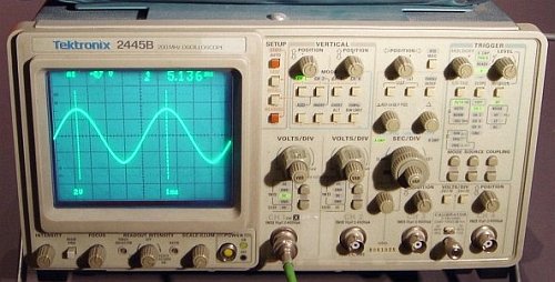
We used an oscilloscope to measure the chargeing time (not the one pictured). Below are the graphs we drew after getting a reading from the oscilloscope. TheCalculations are listed beside them. The calculated timesand the recorded time were very accurate (if not 100%).
How does changes in the resistor affect the charging time?
The bigger the resistor the longer it took the capacitor to reach full capacity. This is because the current was restricted.
How does changes in the capacitor affect the charging time?
When we changed to a bigger capacitor in circuit 4 it too alot longer to charge then the previous capacitor. This is due to the fact that it stores alot more energy so it needs more time to do it.
Here is a list of the different types of capacitors that are found in todays modern electrical items. One thing to note is that some capacitors (mainly the electrolytic type) are prone to explodeing if the polarity is reversed. Make sure you have them facing in the right direction when wiring them in a circuit as it could explode in your face (which might be kinda sore).
Although there are many factors as to how long it will take a capacitor to charge, it will usually charge to 2/3s of it maximum charge in the first 1/5 of its maximum charge time.2/3 of its full charge is often all a circuit will need to function, so designers will want to know this value rather then its fully charged value, so that it can deliver the stored energy as quick as possible.
We used an oscilloscope to measure the chargeing time (not the one pictured). Below are the graphs we drew after getting a reading from the oscilloscope. TheCalculations are listed beside them. The calculated timesand the recorded time were very accurate (if not 100%).
 |
| An oscilloscope used to measure stored energy with wave patterns. Although the wave patterns are not always easy to measure they do give a pretty accurate reading. |
 |
| 3)470*0.0001*5=0.235seconds-235ms |
 |
| 4)41000*0.00033*5=1.65seconds-1650ms |
How does changes in the resistor affect the charging time?
The bigger the resistor the longer it took the capacitor to reach full capacity. This is because the current was restricted.
How does changes in the capacitor affect the charging time?
When we changed to a bigger capacitor in circuit 4 it too alot longer to charge then the previous capacitor. This is due to the fact that it stores alot more energy so it needs more time to do it.
Operational amplifiers (Op amps)
 |
| http://en.wikibooks.org/wiki/Electronics/Op-Amps |
So what are op amps and what do they do? well basially op amp stands for operational amplifier. Its a chip set full of transistors, diodes and capacitors all fabricated into a small and easy to use chip. It is an active component that draws power from an external source to do many different things.
V+ =The non inverting input V- =The inverting input Vout =The output of the other 2 inputs.
VS+ =Positive power supply VS- Negative power supply.Power is drawn from an external power through the VS+ and the VS- into the op amp. The components listed below are inside an op amp and have the following functions.
Diodes= Used to direct the current in the appropriate direction without letting it return back the way it came (AC TO DC).
Transistors= Are basically the diodes set up so that a small current is used through the base to activate the emitter and collector
The capacitors= Are used to create energy and store it for when it is needed. The output energy is usually allot higher than the input energy.
Saying that, an op amp is an active device that can do allot of different things. This makes it useful for any number of different applications. Because of their versatility they are used for anything from laptops and TVs to cars and even planes. Basically anything that needs to have variable inputs and outputs probably has one.
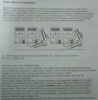
Transistors what they do and how to check them with a meter


No comments:
Post a Comment